Published
- 17 min read
Enterprise Integration Lab
GitHub Repository: Enterprise Integration Lab
1 Project Overview
Enterprise Integration Lab is a local portfolio project that demonstrates how independent enterprise systems can exchange, normalize, synchronize, and observe business data through an event-driven integration lifecycle.
This project was intentionally designed as an industry-neutral enterprise simulation. It does not model any real company, real internal system, or domain-specific production workflow. Instead, it uses generic enterprise concepts such as customers, agreements, service requests, operational cases, documents, canonical business objects, sync logs, and lineage records.
The goal of this project was not simply to build another CRUD application. The goal was to make enterprise integration architecture visible, explainable, and reviewable.
2 Why I Built This Project
Many enterprise systems are not built as one clean monolith. They often grow as separate systems with different responsibilities, data models, lifecycle states, and operational ownership.
A realistic integration platform needs to answer questions such as:
- Where did this request originate?
- Which system owns the raw submission?
- Which system owns the operational workflow?
- How does downstream status affect enterprise-level lifecycle visibility?
- How can documents be stored without mixing binary files into business tables?
- How can integration events be processed asynchronously?
- How can duplicate events avoid creating duplicate downstream records?
- How can auditability and lineage survive across system boundaries?
Enterprise Integration Lab was built to explore those questions in a concrete, runnable system.
3 Final System Overview
The final project includes:
- Docker Compose runtime
- FastAPI backend
- asynchronous worker service
- PostgreSQL with multiple logical schemas
- Redis container
- MinIO document object storage
- static frontend dashboard served through nginx
- reference data layer
- intake portal form
- optional document upload
- event-driven worker lifecycle
- operational case workflow simulation
- canonical business object synchronization
- sync logs
- lineage records
- status history audit trail
- generic demo seed data
- portfolio-ready README and architecture diagrams
The final repository is public-ready and contains only generic demo data.
The main demo surface is a browser-based dashboard served by the frontend container through nginx on port 8080. In the lab environment, I access it from a browser at the Enterprise Lab VM address, for example http://<enterprise-lab-vm-ip>:8080. This dashboard is important because it makes the integration lifecycle visible without requiring a reviewer to inspect PostgreSQL directly.
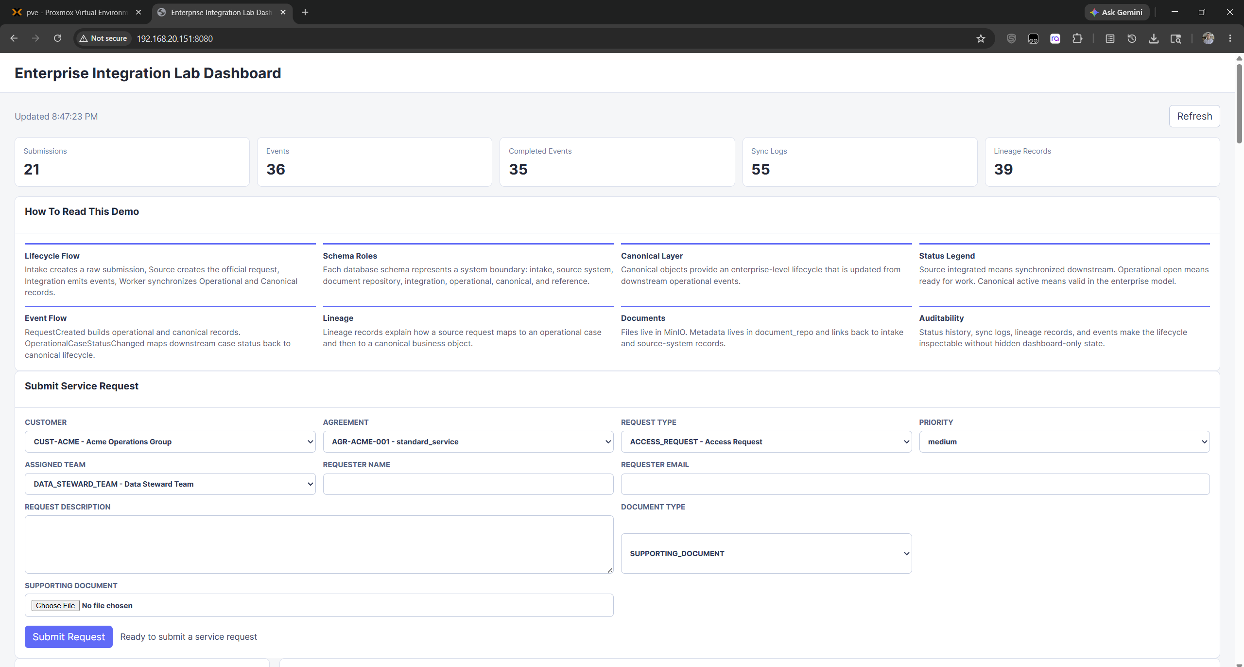 Figure 1. Dashboard overview showing aggregate counts, explanatory panels, intake form, and the main operating surface for the integration demo.
4 Containerized Runtime Architecture
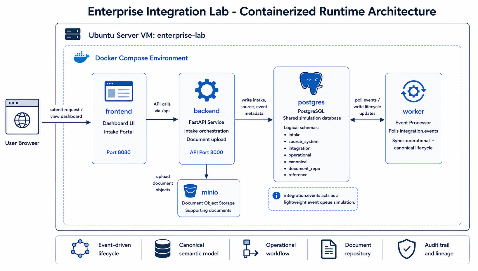
The containerized runtime diagram belongs at the beginning of the architecture discussion because it explains the physical deployment shape before the article moves into data models and event flows. It shows how the user browser, nginx-served frontend, FastAPI backend, PostgreSQL, MinIO, and worker service cooperate inside the Docker Compose environment.
The system runs as a containerized enterprise simulation platform. Each major responsibility is isolated into its own service:
- frontend portal and dashboard
- backend orchestration API
- asynchronous worker processing
- PostgreSQL enterprise data model
- Redis runtime container
- MinIO document repository
The backend handles intake orchestration and read-only dashboard APIs. The worker continuously polls integration events and synchronizes operational and canonical lifecycle state.
This separation was important because it made the system feel closer to an enterprise integration environment rather than a single application with all logic in one place.
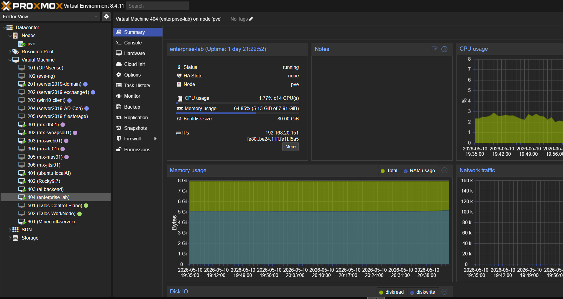 Figure 2. Proxmox runtime view showing the
 enterprise-lab Ubuntu VM running as the infrastructure host for the integration platform.
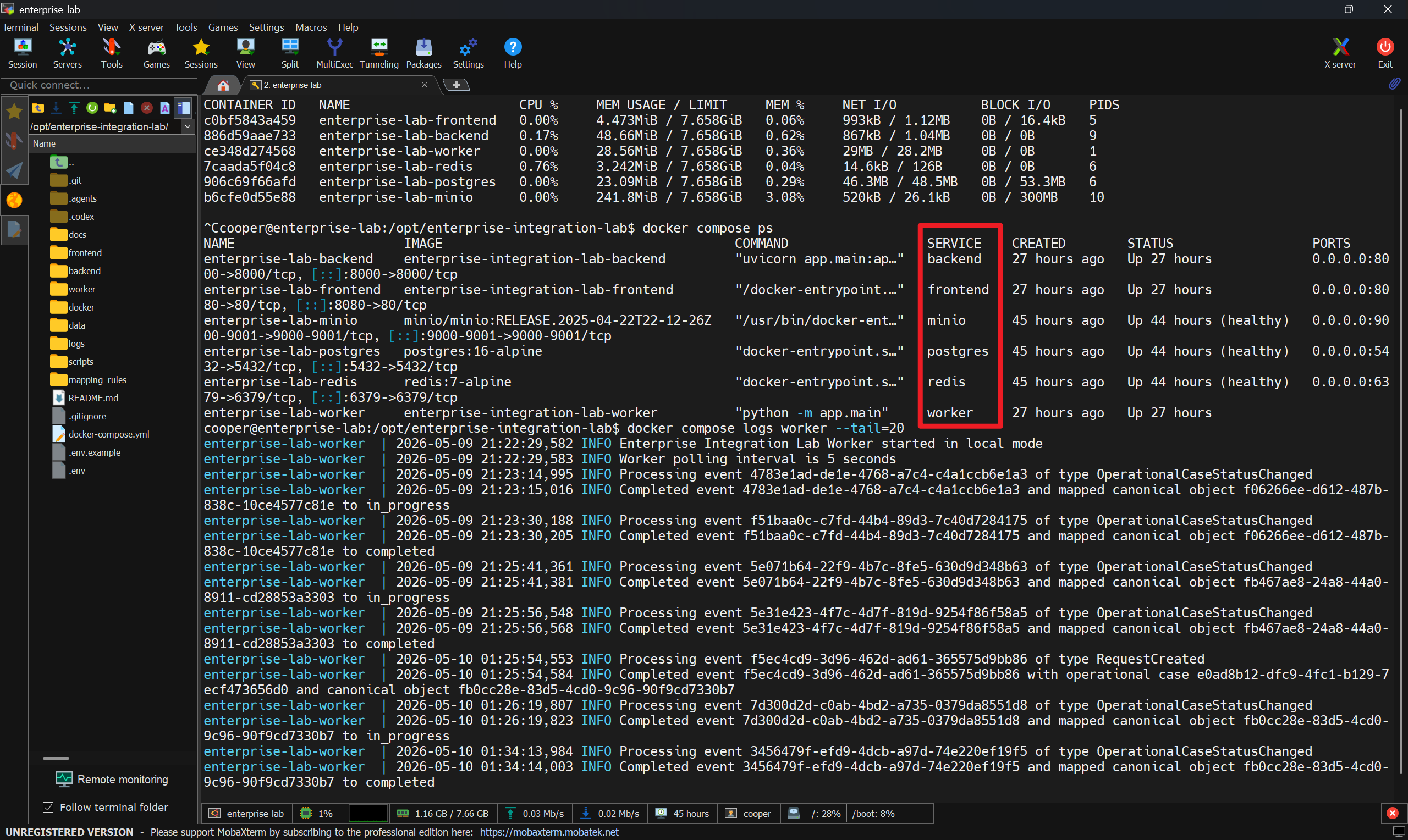 Figure 3. Docker Compose runtime evidence showing the backend, frontend, PostgreSQL, Redis, MinIO, and worker services running, with worker logs processing integration events.
5 Logical Schema Boundaries
PostgreSQL is used not only as a database, but also as a way to express system boundaries.
The project defines multiple logical schemas:
| Schema | Responsibility |
|---|---|
reference | Generic master/reference data used by the intake form |
intake | Raw user-submitted requests |
source_system | First internal source-system request record |
document_repo | Document metadata and object-storage references |
integration | Events and worker sync logs |
operational | Downstream operational case records and status history |
canonical | Enterprise-normalized business objects and lineage |
dashboard | Reserved for future read models |
One of the most important design decisions was to avoid collapsing these responsibilities into a single table or schema. Even though this is a demo project, the schema layout reflects how enterprise systems often need clear ownership boundaries.
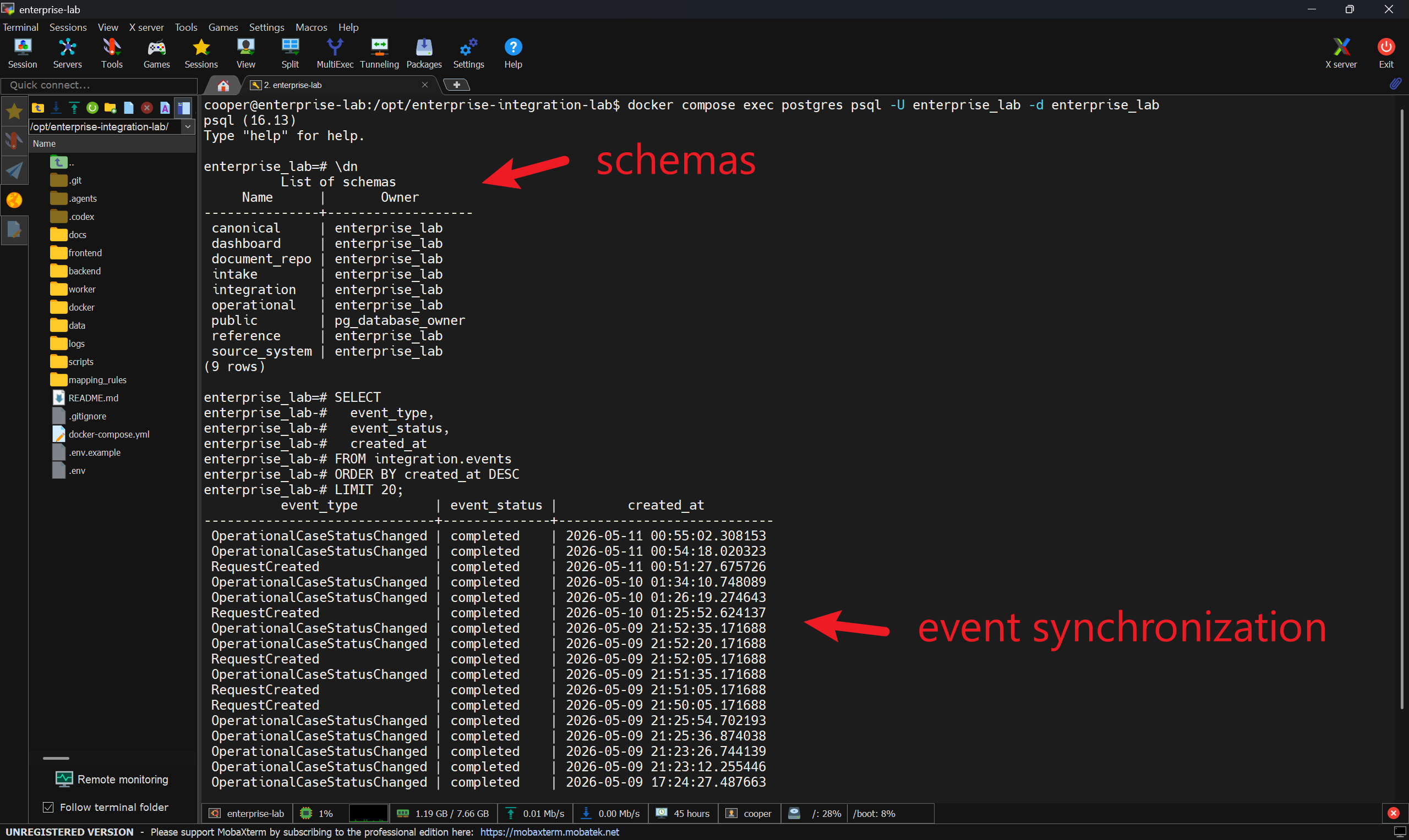 Figure 4. PostgreSQL runtime inspection showing the logical schemas and completed integration events used to verify event synchronization.
6 Event-Driven Enterprise Lifecycle
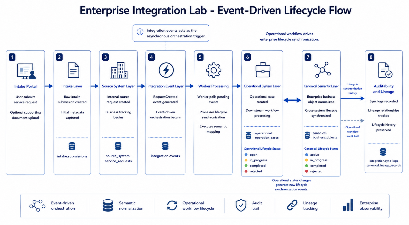
The event-driven lifecycle diagram fits here because it gives the reader the first full end-to-end view of the system behavior. It connects the intake portal, source-system record, integration event, worker processing, operational case, canonical business object, and auditability layer into one visible flow.
The core lifecycle starts when a user submits a service request through the intake portal.
The request moves through several layers:
- The intake layer stores the raw submission.
- The source-system layer creates an internal service request.
- The integration layer records a pending event.
- The worker polls and processes the event asynchronously.
- The operational layer receives or reuses a downstream case.
- The canonical layer creates or updates an enterprise-normalized business object.
- Sync logs and lineage records preserve explainability.
This project demonstrates enterprise lifecycle orchestration rather than simple CRUD processing. The API does not directly create every downstream object. Instead, it creates source records and integration events. The worker is responsible for asynchronous synchronization.
That distinction became one of the most important architectural lessons in the project.
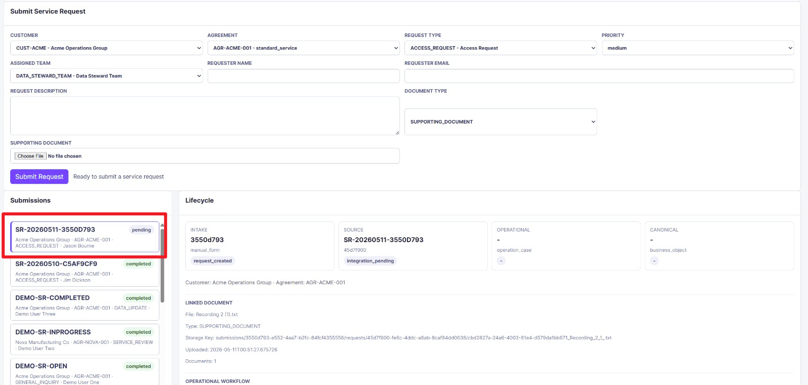 Figure 5. Newly submitted request entering the system as
 pending, before the asynchronous worker creates downstream operational and canonical records.
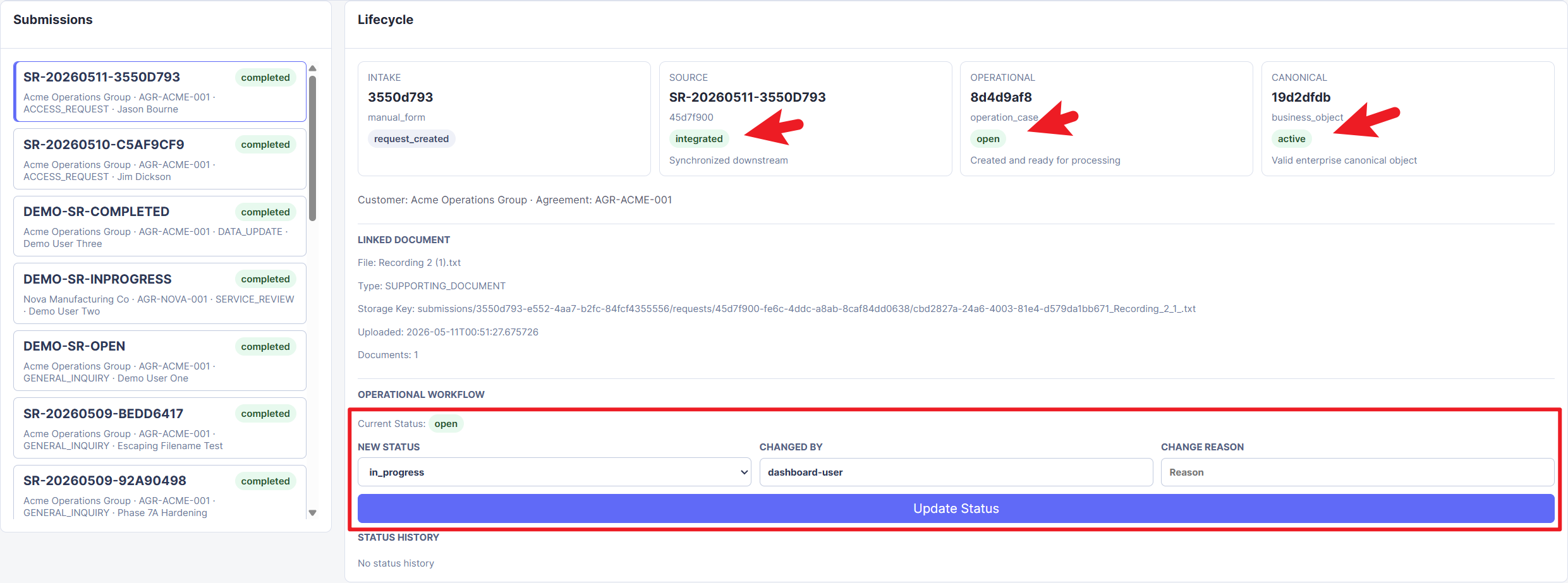 Figure 6. Worker-processed submission showing the source request as
 integrated, the operational case as open, and the canonical business object as active.
7 Semantic Mapping and Enterprise Lineage
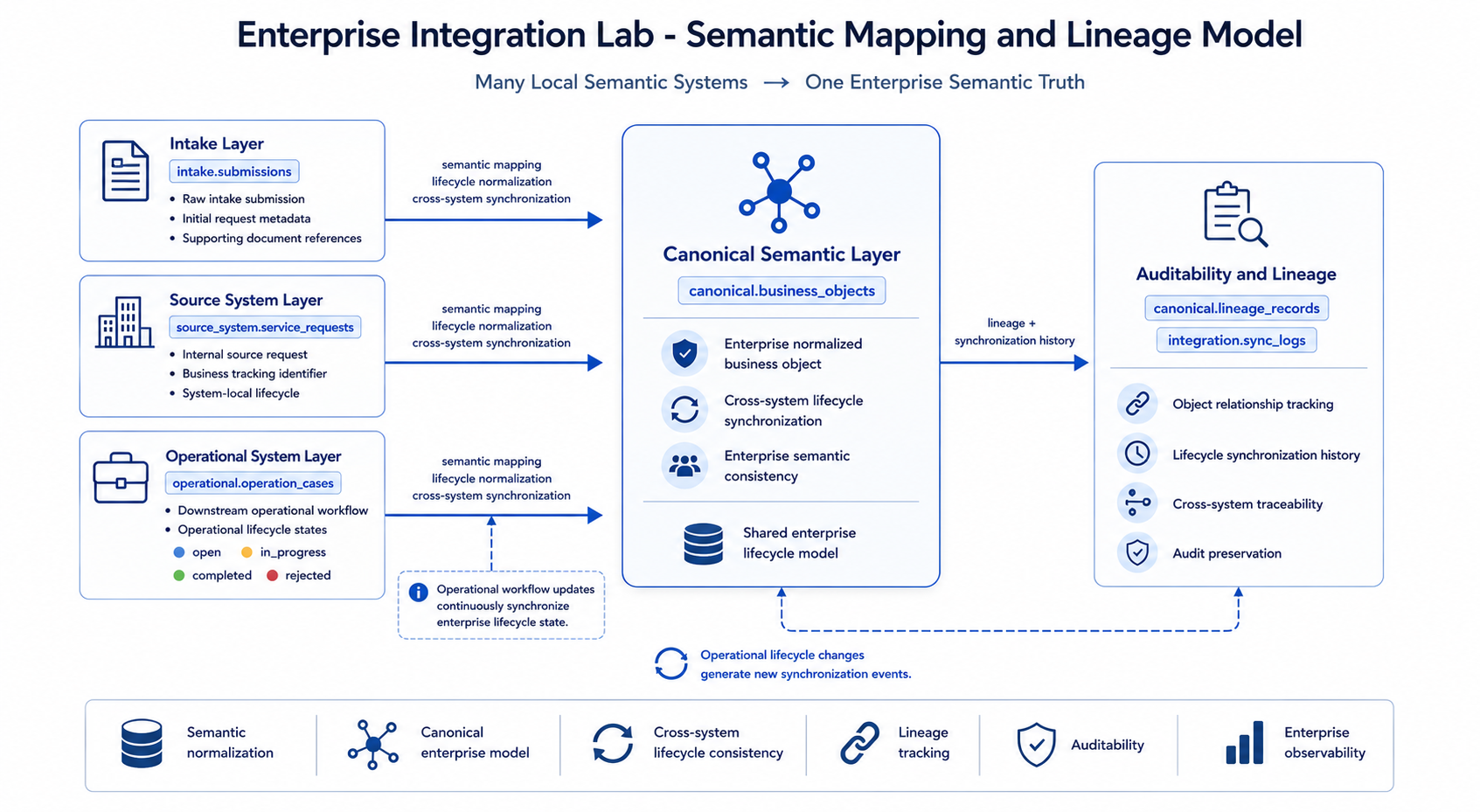
The semantic mapping and lineage diagram belongs in this section because it explains the conceptual purpose of the canonical layer. It shows how local meanings from intake, source-system, and operational layers are normalized into one enterprise semantic view while lineage and synchronization history remain auditable.
Different enterprise systems often describe similar business concepts in different ways.
In this project:
- intake submissions represent raw user input
- source requests represent internal source-system records
- operational cases represent downstream work records
- canonical business objects represent enterprise-normalized semantics
The canonical layer behaves like a shared enterprise semantic coordinate system. It does not replace local systems. Instead, it provides a consistent enterprise-level view across otherwise independent operational systems.
Lineage records preserve relationships such as:
- source request to operational case
- operational case to canonical business object
This allows the dashboard and SQL queries to explain how data moved through the system.
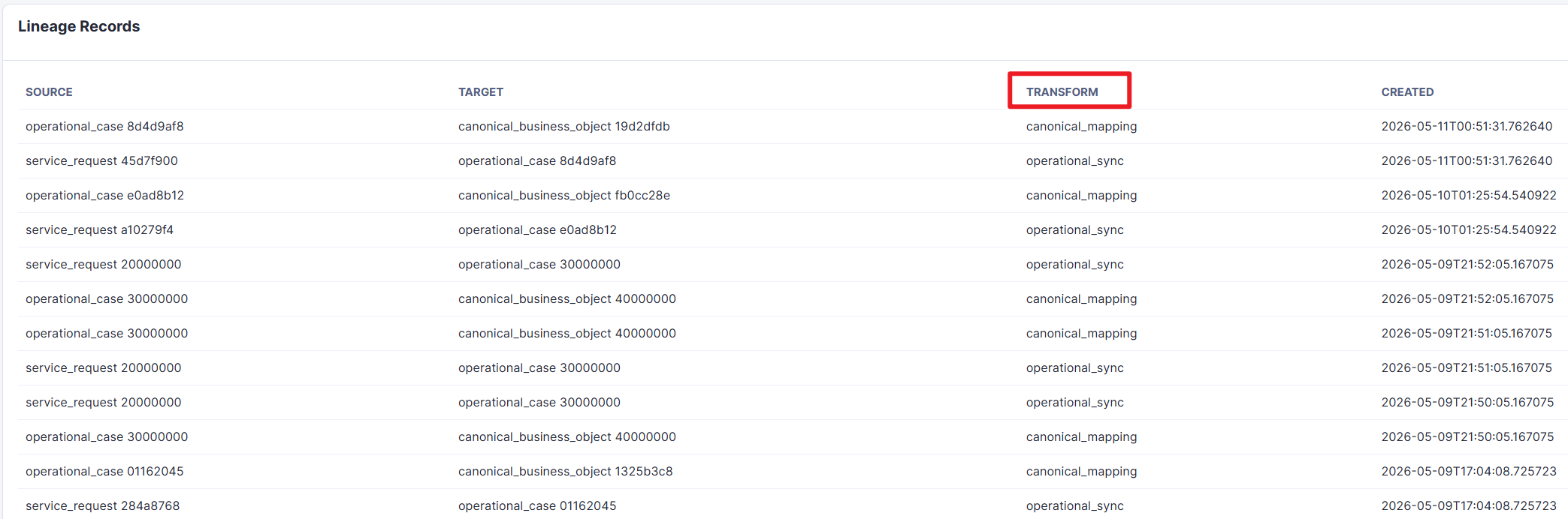 Figure 7. Lineage records showing how service requests map to operational cases and how operational cases map to canonical business objects.
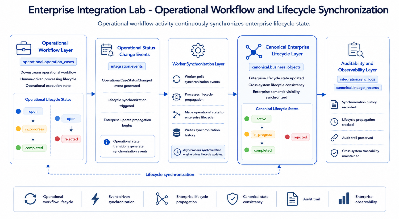
8 Operational Workflow and Lifecycle Synchronization
The operational workflow diagram is placed after the semantic model because it zooms into one of the most important feedback loops: downstream operational activity continuously updates the enterprise lifecycle state through integration events and worker synchronization.
The operational system simulates downstream human workflow.
Operational cases can move through these states:
openin_progresscompletedrejected
Allowed transitions are intentionally simple:
open -> in_progressopen -> rejectedin_progress -> completedin_progress -> rejected
Completed and rejected cases are terminal.
Each operational status change writes:
- previous status
- new status
- changed by
- change reason
- changed timestamp
It also creates an OperationalCaseStatusChanged integration event. The worker processes that event and updates the canonical lifecycle status asynchronously.
The mapping is:
| Operational Status | Canonical Status |
|---|---|
open | active |
in_progress | in_progress |
completed | completed |
rejected | rejected |
This preserves local operational independence while keeping enterprise lifecycle visibility synchronized centrally.
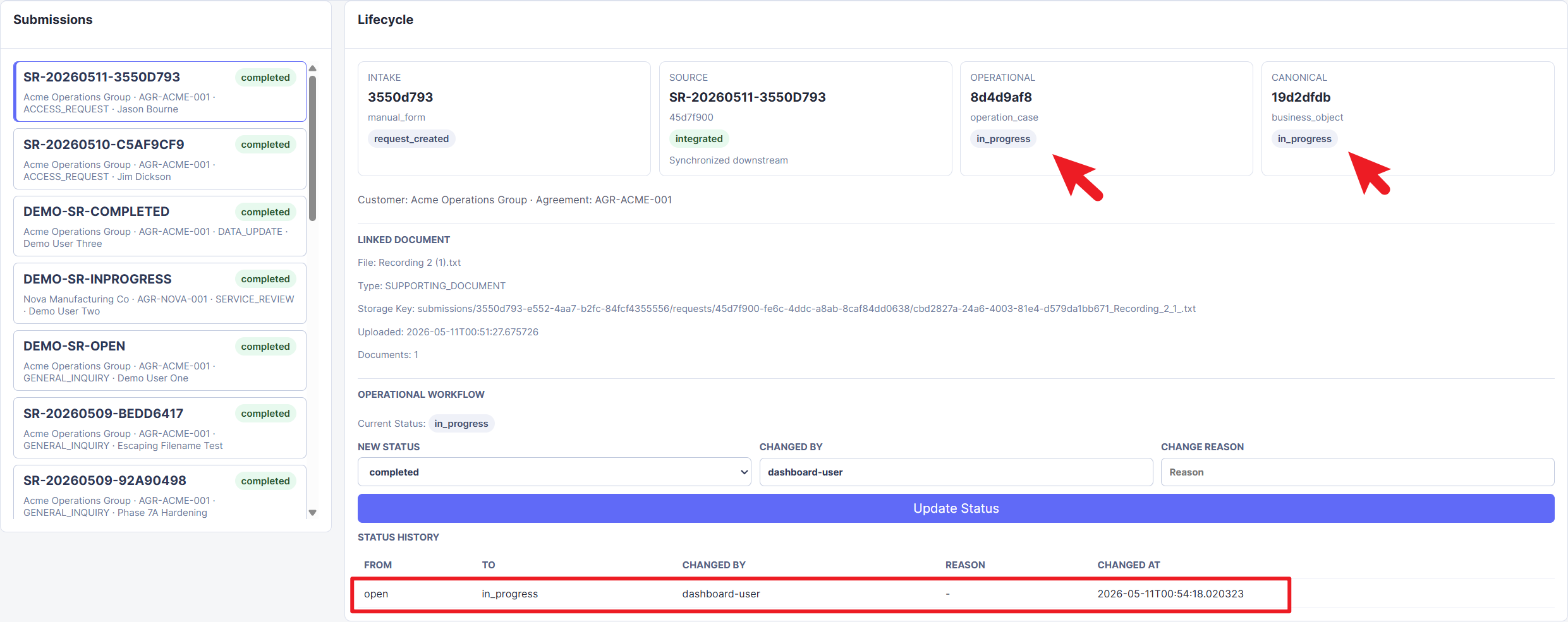 Figure 8. Operational case after being moved to
 in_progress, with the canonical lifecycle state synchronized to match the downstream workflow state.
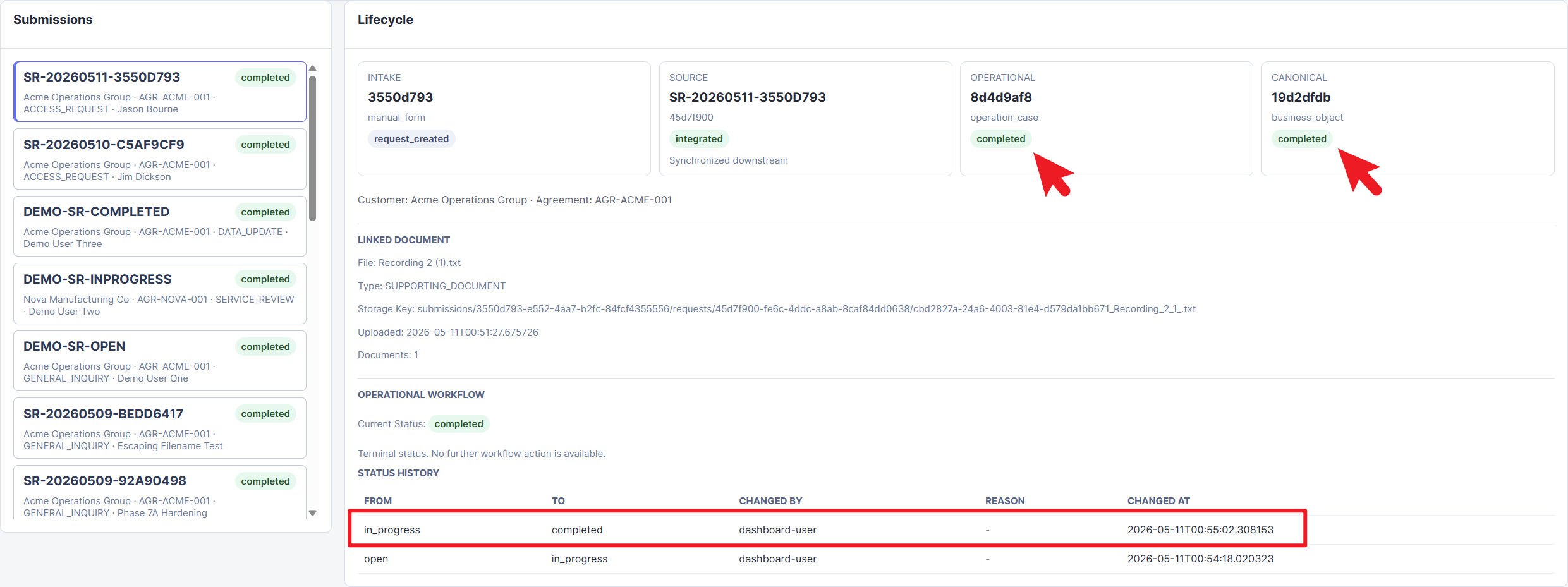 Figure 9. Completed operational case showing terminal lifecycle state and status history, preserving the transition from
 open to in_progress to completed.
9 Document Repository Flow
The project includes an optional document upload flow.
When a user submits a service request, they can upload one supporting document. The binary file is stored in MinIO, while metadata is stored in PostgreSQL under document_repo.documents.
The metadata includes:
- document ID
- linked submission ID
- linked request ID
- file name
- document type
- storage key
- upload timestamp
This design keeps binary object storage separate from relational business records.
The dashboard displays document metadata, but it does not preview or download files. That was an intentional scope boundary for the MVP.
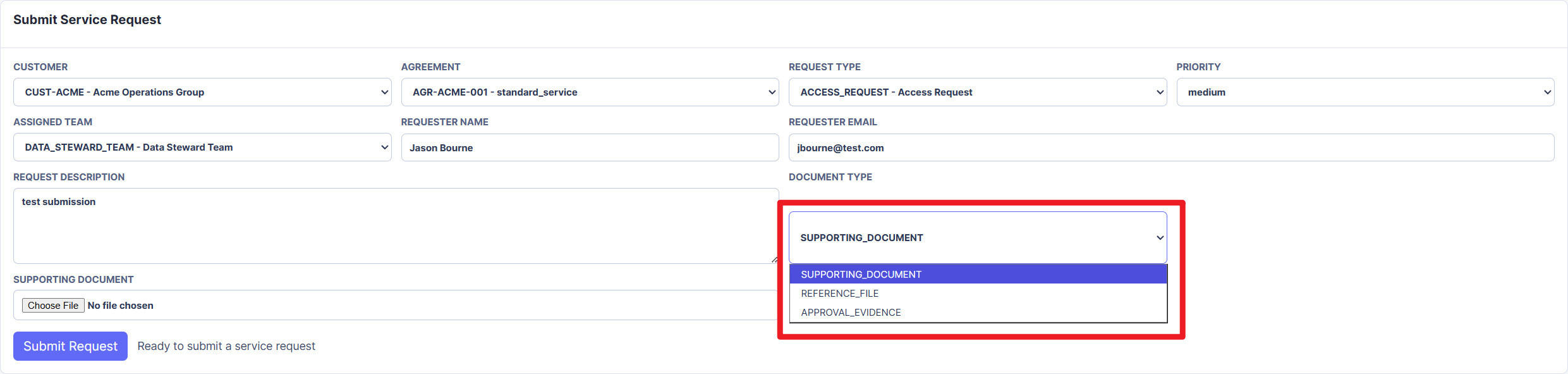 Figure 10. Intake portal document type selector showing how supporting documents are classified before upload.
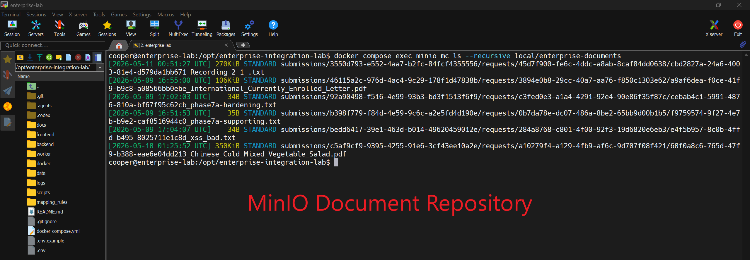 Figure 11. MinIO repository inspection showing uploaded supporting documents stored as objects outside the relational business tables.
10 Reference Data Layer
A later phase introduced a generic reference data layer.
The purpose was to avoid letting users type arbitrary customer or agreement data into the intake form. Instead, the form uses controlled reference data from backend APIs.
Reference tables include:
reference.customersreference.agreementsreference.request_typesreference.teams
This made the portal feel more enterprise-like. Users select known reference data rather than submitting free-form values that may not exist in upstream systems.
An important follow-up improvement was replacing embedded reference data in request_description with structured customer_id and agreement_id fields. This was a useful modeling correction: enterprise relationships should be structured data, not hidden inside text.
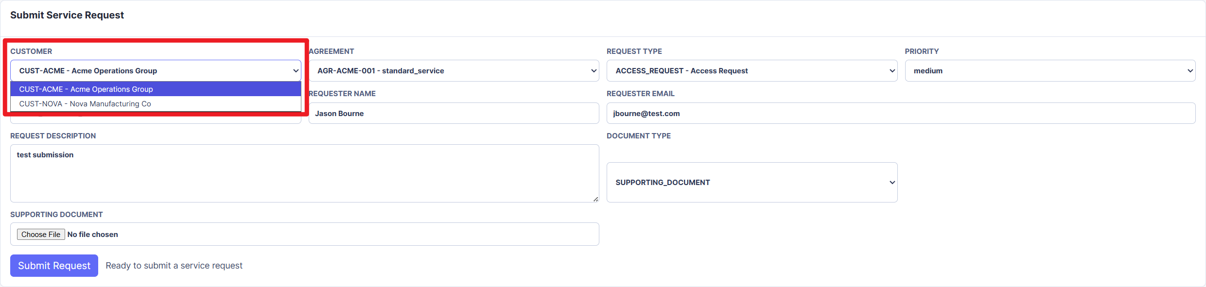 Figure 12. Customer reference selector showing controlled customer choices loaded from the reference data layer.
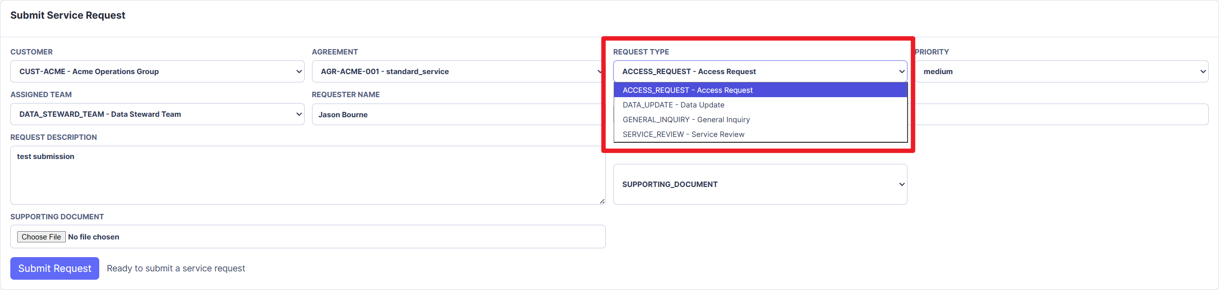 Figure 13. Request type selector showing standardized service request classifications instead of free-form request categories.
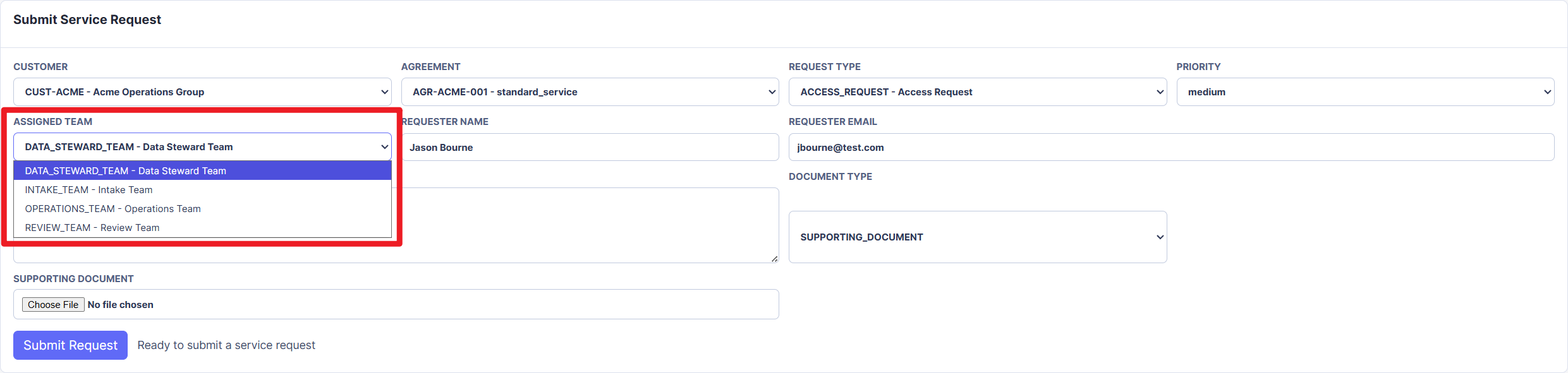 Figure 14. Assigned team selector showing operational ownership choices represented as controlled reference data.
11 Dashboard and Observability
The dashboard is the main demo surface.
It shows:
- submissions
- source requests
- operational cases
- canonical business objects
- event statuses
- sync logs
- lineage records
- document metadata
- status history
- lifecycle explanation
- schema role legend
- status meaning legend
The dashboard is intentionally read-only for lifecycle data, except for the controlled operational workflow action that simulates downstream human processing.
The dashboard was important because it turned database records into an explainable architecture story. Without it, the system could only be understood through SQL queries.
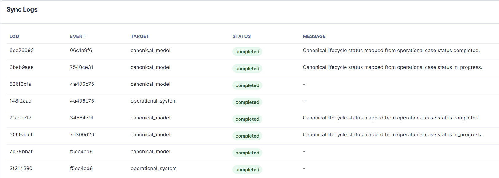 Figure 15. Sync log table showing completed worker actions and status propagation messages for operational-to-canonical lifecycle synchronization.
12 Implementation Journey
The project evolved through multiple phases. Each phase added one architectural layer or corrected one modeling issue.
Phase 1: Infrastructure Skeleton
The first milestone created the basic runtime foundation:
docker-compose.yml- FastAPI backend skeleton
- worker service skeleton
- PostgreSQL container
- Redis container
- MinIO container
- frontend placeholder
.env.example- README setup instructions
At this stage, no business logic was implemented. The goal was to establish the containerized structure first.
The main lesson was that architecture should be made visible before implementation details grow around it.
Phase 2: Database Schema Layer
The second milestone implemented the database schema layer.
Tables were created across logical schemas for:
- raw intake
- source system records
- integration events
- canonical objects
- operational records
- document metadata
- reference data
- sync logs
- lineage records
The schema included:
- UUID business IDs
- primary keys
- foreign keys
- indexes
- status check constraints
- JSONB fields where appropriate
created_atandupdated_attimestamps
This phase established the system boundary model that guided the rest of the project.
Phase 3A: Minimal Event-Driven Lifecycle
The first working lifecycle implemented:
POST /intake/submissions- write
intake.submissions - create
source_system.service_requests - create
integration.events - worker polls pending events
- worker creates
canonical.business_objects - worker writes
integration.sync_logs
This was the point where the project stopped being static infrastructure and became a working integration simulation.
Phase 3B: Architecture Boundary Review
After the first lifecycle worked, I reviewed whether the API and worker responsibilities were cleanly separated.
The review focused on:
- whether the API was doing work that belonged to the worker
- whether source, integration, and canonical layers remained distinct
- whether transaction handling was safe
- whether worker polling could duplicate processing
- whether event status updates were explainable
- whether sync logs and lineage records told a complete story
The review found several risks that needed hardening before adding more features.
Phase 3C: Worker Hardening
This phase addressed critical stability issues.
The key improvements were:
- worker idempotency
- deterministic source references
- unique constraints to prevent duplicate canonical objects
- safe rollback on worker failure
- failed sync log recording in a new transaction
- cleaner backend service boundaries
The backend was refactored into service modules:
- intake service
- source system service
- integration event service
This made the code structure match the architecture more clearly.
The biggest lesson was that event-driven systems need idempotency early. Without it, duplicate events can quietly corrupt downstream data.
Phase 4: Operational System Sync
The next phase added the downstream operational system.
When the worker processed a RequestCreated event, it now created or reused:
operational.operation_casescanonical.business_objects
It also wrote lineage records for:
- service request to operational case
- operational case to canonical business object
This phase made the project feel much more like an enterprise integration scenario. The source request was no longer just normalized into a canonical object; it also produced a downstream operational record.
Phase 5: Observability Dashboard
The project then added read-only dashboard APIs and a frontend dashboard.
Backend APIs included:
GET /dashboard/submissionsGET /dashboard/submissions/{submission_id}GET /dashboard/eventsGET /dashboard/lineageGET /dashboard/sync-logs
The frontend changed from a placeholder into a basic lifecycle dashboard.
This surfaced a practical deployment bug: the frontend JavaScript originally called localhost:8000. That worked inside the VM, but failed when accessing the dashboard from another machine on the LAN because browser localhost referred to the viewer’s machine.
The fix was to use nginx reverse proxy routing:
- frontend requests
/api/... - nginx proxies
/apitobackend:8000
This was a useful reminder that browser networking context is different from container or VM networking context.
Phase 6A: Reference Data Layer
This phase added generic enterprise reference data:
- customers
- agreements
- request types
- teams
The backend exposed read-only reference APIs so the portal could load controlled dropdown values.
This avoided a common data quality problem: allowing portal users to type values that do not exist in enterprise master data.
Phase 6B: Intake Portal Form
The dashboard gained a basic intake portal form.
The form allowed users to select:
- customer
- agreement
- request type
- priority
- assigned team
It also collected:
- requester name
- requester email
- request description
At first, selected customer and agreement values were embedded into the request description. That worked technically, but it was not good enterprise modeling.
Phase 6C: Structured Reference Fields
The next correction moved customer and agreement references into structured fields:
customer_idagreement_id
These fields were added to both:
intake.submissionssource_system.service_requests
Foreign keys linked them to the reference schema.
This was a valuable modeling lesson: text is not a substitute for relationships. If a concept has identity and referential meaning, it should be modeled structurally.
Phase 6D: Status Semantics Cleanup
The dashboard originally showed statuses such as:
- source:
integration_pending - operational:
pending
Even after the worker had successfully processed the event, these labels made the system look unfinished.
The status semantics were cleaned up:
- source request becomes
integrated - operational case starts as
open - canonical object remains
active
The README and dashboard were updated to explain:
- source
integratedmeans the source request has been synchronized downstream - operational
openmeans the downstream case has been created and is ready for processing - canonical
activemeans the enterprise canonical object is valid and active
The lesson was that technically valid statuses can still be misleading to users. Status names are part of the architecture interface.
Phase 7A: Document Repository and Attachment Flow
This phase connected the document repository to the intake lifecycle.
The portal form gained an optional file input. The backend accepted multipart form data, uploaded the file to MinIO, and wrote metadata to document_repo.documents.
The document metadata linked to both:
- the intake submission
- the source service request
The lifecycle itself stayed unchanged. Documents became attached context, not drivers of workflow logic.
Phase 7B: Document Upload Risk Analysis
The document upload implementation was reviewed for consistency, transaction safety, idempotency, and security.
The review identified several risks:
- MinIO upload failure could leave partial lifecycle state depending on transaction boundaries
- MinIO upload success followed by database failure could create orphan objects
- no file size limit
- no file type allowlist
- possible frontend XSS risk if document metadata was inserted through unsafe
innerHTML
This review was one of the most valuable parts of the project because it exposed the difference between “feature works” and “feature is safe enough for a demo.”
Phase 7C: Document Upload Hardening
The hardening phase fixed the most important issues:
- best-effort MinIO cleanup if metadata insert fails
- 10MB upload limit
- file extension allowlist
- content type allowlist
- safer frontend rendering for user-controlled text
Allowed MVP file types became:
- TXT
- CSV
- PNG
- JPEG
The README documents that validation is MVP-level and does not inspect magic bytes.
Phase 7D: Operational Workflow Simulation
The final functional feature added operational case workflow.
The backend added:
PATCH /operational/cases/{operation_case_id}/status
The database added:
operational.case_status_history
Each status update:
- validates the transition
- updates the operational case
- writes status history
- creates an
OperationalCaseStatusChangedevent - lets the worker propagate status to the canonical layer
This completed the core integration loop: downstream operational activity can now update enterprise lifecycle visibility asynchronously.
13 Portfolio Readiness Remediation
After the functional phases, the project was reviewed as a public portfolio artifact.
The review focused on:
- architecture clarity
- dashboard explainability
- README quality
- terminology safety
- demo data hygiene
- public GitHub readiness
The remediation phase added:
.gitignore- removal of tracked
.env - clean reset/reseed instructions
- generic demo seed data
- portfolio-oriented README sections
- Mermaid architecture diagram
- dashboard explanation panels
- architecture diagrams in
docs/assets - security notes
- production-readiness disclaimer
The final README was shaped as an architecture portfolio entry, not just a developer runbook.
Public Repository Privacy Hardening
Before making the repository public, I performed a privacy and hygiene review.
The review checked:
- tracked files
- Git history
.envexposure- author email
- tokens and private keys
- real email addresses
- local paths
- LAN IP addresses
- uploaded file metadata
- domain-specific terminology
Two important issues were found:
.envhad existed in earlier Git history.- commit author metadata exposed a real email address.
The repository history was then rewritten into a single clean public commit using a privacy-preserving noreply-style email. The old history was force-pushed away from the public branch.
This step was important because removing a file from the latest commit is not the same as removing it from Git history.
14 Key Technical Lessons
1. Event-driven systems need idempotency from the beginning
A worker may process the same event more than once. Without deterministic references and uniqueness constraints, duplicate events can create duplicate downstream records.
The project solved this by using deterministic source references and reusing existing canonical and operational records where appropriate.
2. Rollback handling must account for aborted transactions
When PostgreSQL transactions fail, the transaction can enter an aborted state. If failure logging happens inside the same broken transaction, the failure log may not be written.
The worker was hardened to rollback first, then open a new transaction to record failure status and sync logs.
3. Architecture boundaries should be reflected in code structure
The backend originally handled intake, source request creation, and event creation in one flow. That behavior was acceptable, but the code structure needed clearer boundaries.
Refactoring into service modules made the code easier to reason about:
- intake service
- source system service
- integration service
- document service
- operational service
- dashboard service
4. Browser networking is not container networking
The dashboard initially failed from a LAN browser because frontend JavaScript called localhost:8000.
The fix was to route API calls through nginx using relative paths:
- browser calls
/api/... - nginx proxies to
backend:8000
This made the dashboard usable from other machines without changing backend business logic.
5. Structured relationships beat embedded text
Putting selected customer and agreement information into request_description worked temporarily, but it was not correct enterprise modeling.
Moving those fields into structured UUID relationships made the data model more reliable, queryable, and explainable.
6. Status names matter
A technically correct status can still confuse users.
Changing integration_pending to integrated and pending to open made the dashboard easier to understand without changing the underlying architecture.
7. Object storage and database transactions do not rollback together
MinIO uploads and PostgreSQL transactions are separate systems.
If a file upload succeeds but metadata insert fails, the object can become orphaned. The project added best-effort cleanup to reduce this risk.
8. Portfolio readiness is part of engineering
A project can be technically functional but still not ready to show publicly.
Public readiness required:
- README storytelling
- diagrams
- demo data hygiene
.envcleanup- Git history cleanup
- security disclaimers
- clear scope boundaries
15 What This Project Is Not
This project is not production ready.
It intentionally does not include:
- authentication
- role-based authorization
- TLS termination
- production secret management
- malware scanning
- document preview/download
- AI normalization implementation
- complex retry policies
- distributed locking
- production observability stack
- public internet deployment hardening
These omissions are documented because portfolio projects should be honest about scope.
16 Current Demo Workflow
A reviewer can run the project locally and follow this flow:
- Start the stack with Docker Compose.
- Open the dashboard.
- Review seeded demo records.
- Submit a new service request.
- Optionally upload a supporting document.
- Watch the worker process the event.
- Review operational and canonical records.
- Move the operational case to
in_progress. - Complete or reject the operational case.
- Review status history, sync logs, events, and lineage.
This gives a complete end-to-end demonstration of the integration lifecycle.
17 Final Architecture Value
The final system demonstrates several enterprise architecture concepts in one small project:
- system boundary separation
- event-driven orchestration
- asynchronous worker processing
- source-system records
- downstream operational records
- canonical data modeling
- document repository separation
- reference data governance
- lineage and auditability
- lifecycle observability
- public-ready project documentation
What I like most about this project is that it does not rely on one impressive feature. Its value comes from the relationships between layers.
The system is small enough to run locally, but structured enough to explain real enterprise integration concerns.
18 Future Improvements
The next possible improvements would be:
-
AI-assisted intake normalization
Add AI suggestions for request classification and metadata extraction while keeping deterministic validation and synchronization as the source of truth. -
Document preview and download
Add secure document retrieval with signed URLs or backend-mediated access. -
Advanced workflow rules
Add richer transition rules, assignment logic, and escalation states. -
Retry and dead-letter handling
Improve worker resilience with retry counts, exponential backoff, and dead-letter event states. -
Production-style observability
Add metrics, structured logs, tracing, and operational dashboards. -
Migration framework
Replace init SQL rebuilds with a formal migration tool such as Alembic.
19 Reflection
This project started as a simple infrastructure skeleton and gradually became a complete enterprise integration simulation.
The most useful parts of the process were not only the features that were added, but the reviews that found architectural and operational weaknesses:
- worker idempotency
- transaction failure handling
- dashboard networking
- structured reference modeling
- status semantics
- document upload safety
- XSS prevention
- public repository hygiene
Those corrections made the project stronger and also made the learning more concrete.
Enterprise architecture is not just about drawing boxes. It is about defining ownership, preserving meaning across boundaries, handling failure honestly, and making system behavior explainable.
Enterprise Integration Lab became a portfolio project because it demonstrates those ideas in a working, reviewable, runnable form.