Published
- 4 min read
Network Simulation Project – VLANs, Firewalls, NAT & VPN
🧩 Enterprise Network Simulation — VLANs, Firewalls, NAT & VPN
Summary: A comprehensive enterprise network simulation project designed and deployed in GNS3 (running on my Proxmox HomeLab). It demonstrates end-to-end connectivity, segmentation, and security implementation between a Head Office and a Branch Office, integrating VLANs, OSPF, Palo Alto firewalls, NAT, and IPSec VPN.
🎯 Project Overview
This project replicates the IT infrastructure of a mid-size enterprise with one Head Office and one Branch Office located in different geographic regions.
It combines multiple networking technologies to achieve secure, reliable, and segmented communication between sites.
All configurations were implemented and tested in GNS3, hosted within my Proxmox-based HomeLab, to ensure full isolation, persistence, and realistic behavior of enterprise equipment.
🧠 Objectives
-
Build a hub-and-spoke network topology connecting two offices through an IPSec site-to-site VPN.
-
Implement VLAN segmentation for departmental separation and inter-VLAN routing through firewalls.
-
Configure OSPF for dynamic routing across internal and ISP networks.
-
Design and enforce firewall security zones and policies for traffic control.
-
Apply NAT for outbound internet access and public web server exposure.
-
Validate the full network with functional and security testing.
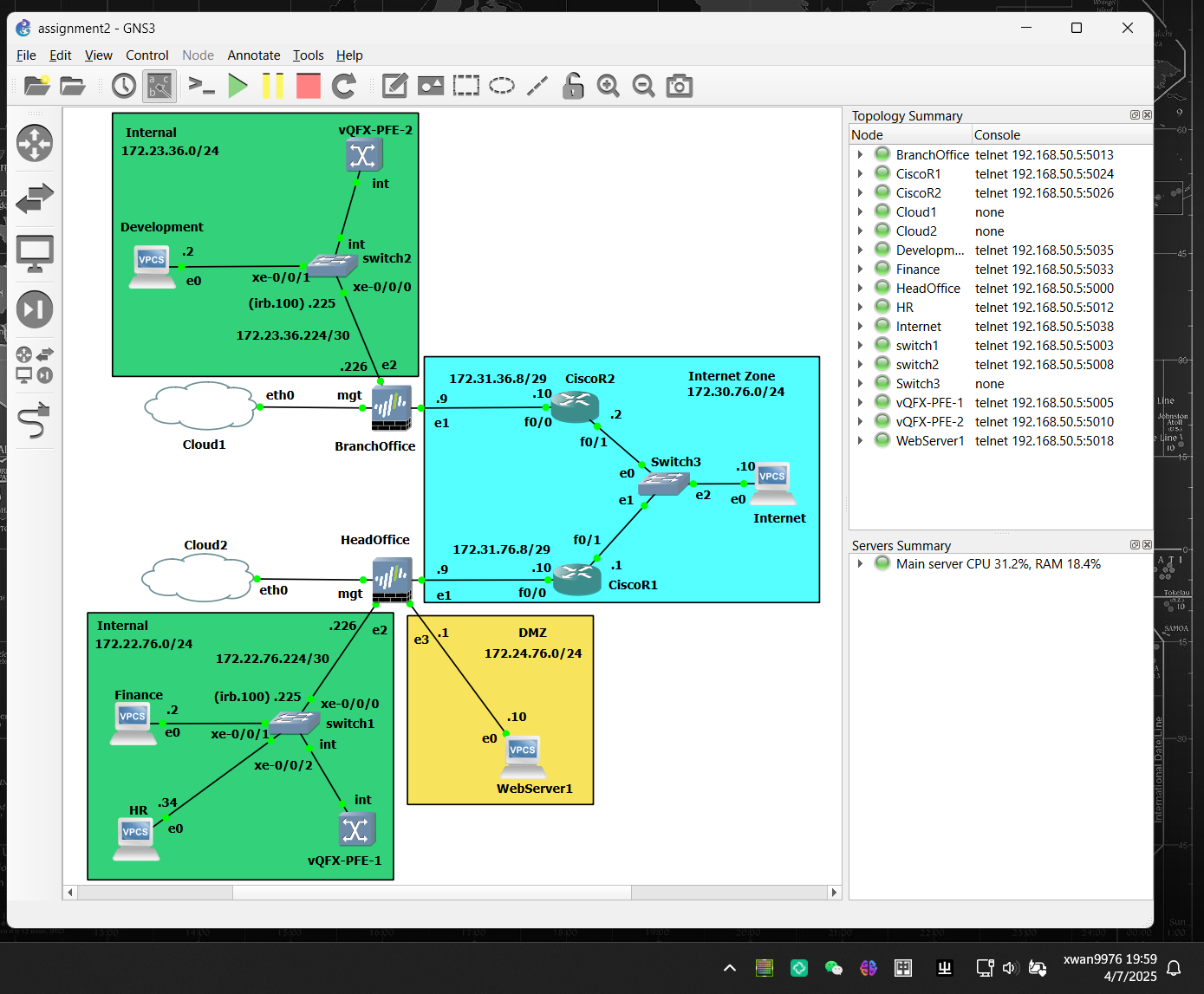
🏗️ Topology Design
The network consists of the following major components:
| Site | Device | Role | Virtualization Image |
|---|---|---|---|
| Head Office | Router (ISP) | Internet gateway | Cisco 3725 |
| Head Office | Firewall | Security boundary, NAT, VPN | Palo Alto v11.0 |
| Head Office | Switch | VLAN and IRB routing | Juniper vQFX-20.2R1 |
| Branch Office | Router (ISP) | Internet gateway | Cisco 3725 |
| Branch Office | Firewall | Security boundary, VPN | Palo Alto v11.0 |
| Branch Office | Switch | VLAN segmentation | Juniper vQFX-20.2R1 |
Network Architecture Diagram:
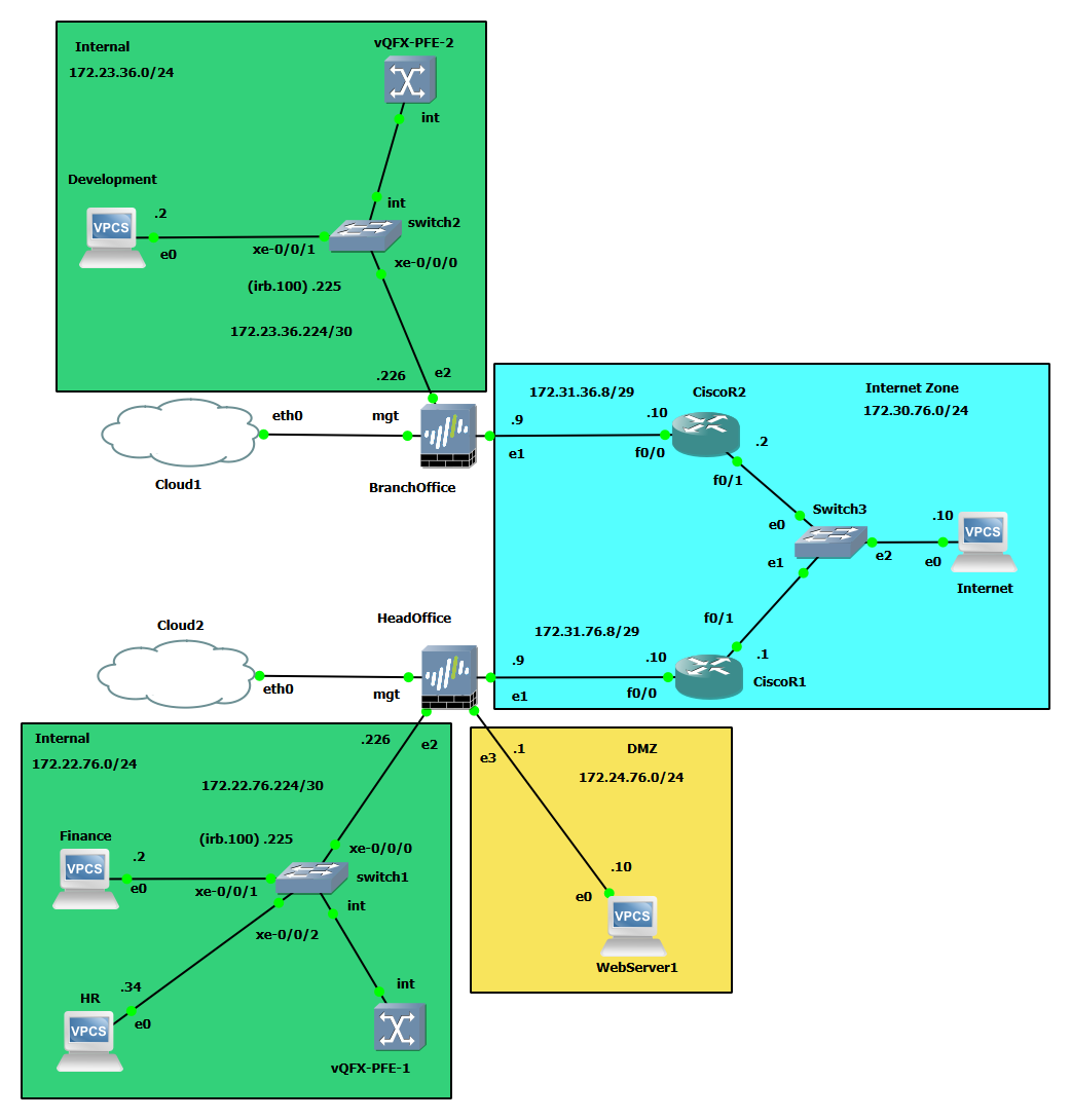
The Internet layer was simulated using two ISP routers with OSPF in area 0 to provide a realistic WAN environment.
🧩 VLAN Design & Implementation
Each office was segmented into logical VLANs to emulate real departments and control broadcast domains.
HQ VLANs:
| Department | VLAN ID | Subnet | IRB Interface |
|---|---|---|---|
| Finance | 10 | 172.22.76.0/27 | irb.10 |
| HR | 20 | 172.22.76.32/27 | irb.20 |
| Operations | 30 | 172.22.76.64/27 | irb.30 |
| Customer Service | 40 | 172.22.76.96/27 | irb.40 |
| Routing | 100 | 172.22.76.224/30 | irb.100 |
| DMZ (Web Server) | — | 172.24.76.0/24 | — |
Branch VLANs:
| Department | VLAN ID | Subnet | IRB Interface |
|---|---|---|---|
| Development | 10 | 172.23.36.0/27 | irb.10 |
| Test | 20 | 172.23.36.32/27 | irb.20 |
| Management | 30 | 172.23.36.64/27 | irb.30 |
| Routing | 100 | 172.23.36.224/30 | irb.100 |
Each VLAN was assigned to a firewall zone to ensure granular control at Layer 3.
🔥 Firewall Configuration
The Palo Alto firewalls served as the security boundary for both sites.
Configuration highlights include:
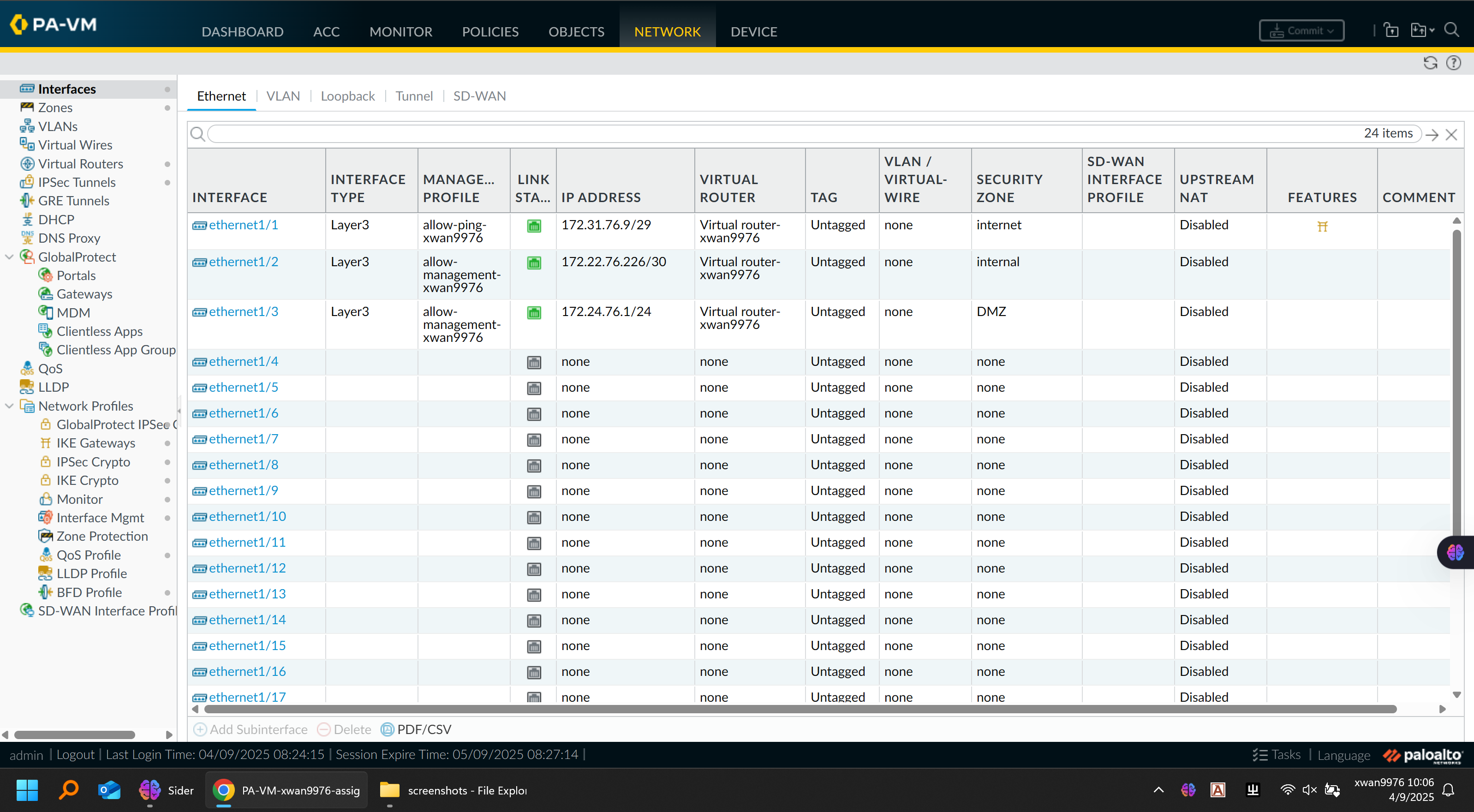
🔹 Zone & Interface Setup
-
Defined zones:
LAN,VPN,DMZ,Untrust, andManagement -
Assigned corresponding interfaces (e.g.,
ethernet1/1→ LAN,ethernet1/2→ Untrust) -
Enabled management profiles for SSH and HTTPS control-plane access
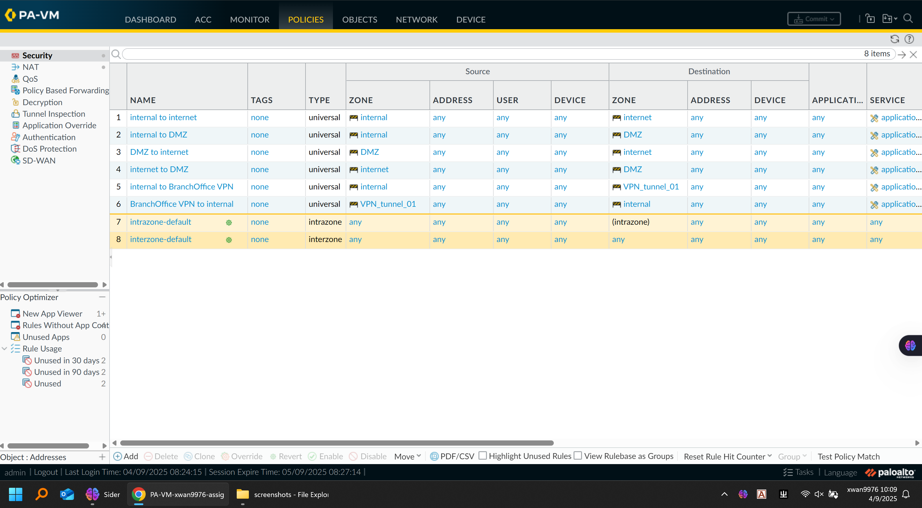
Firewall Security Policy:
Firewall Interfaces Configuration Figre:
🔹 Security Policies
| Source Zone | Destination Zone | Action | Description |
|---|---|---|---|
| LAN → Untrust | Allow | Internet access for all internal departments | |
| DMZ → Untrust | Allow | Outbound access for web server updates | |
| VPN → LAN | Allow | Inter-site communication | |
| Any → Management | Deny | Restrict administrative access | |
| Untrust → DMZ | Allow (port 80/443) | Permit inbound web traffic to HQ server | |
| Untrust → LAN | Deny | Prevent unsolicited inbound connections |
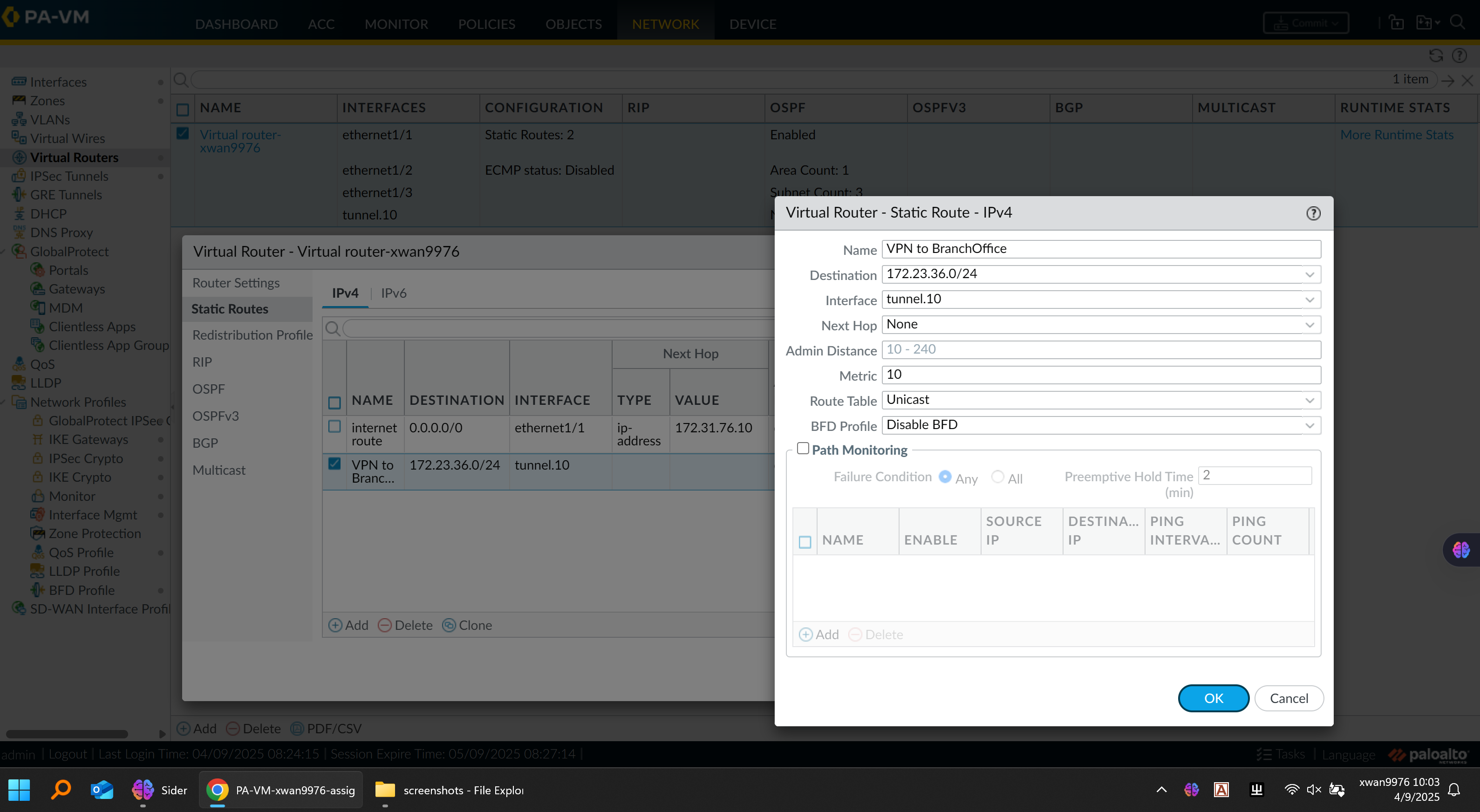
🔹 Virtual Router
-
Configured static routes for local subnets
-
Redistributed connected networks into OSPF where appropriate
-
Excluded internet-facing zones from OSPF advertisement to prevent leakage
Virtual Router Configuration:
🔹 Firewall Testing
-
Verified NAT and VPN traffic using the Monitor tab
-
Used advanced ping:
ping source <source IP> host <destination IP>to confirm reachability through specific firewall interfaces
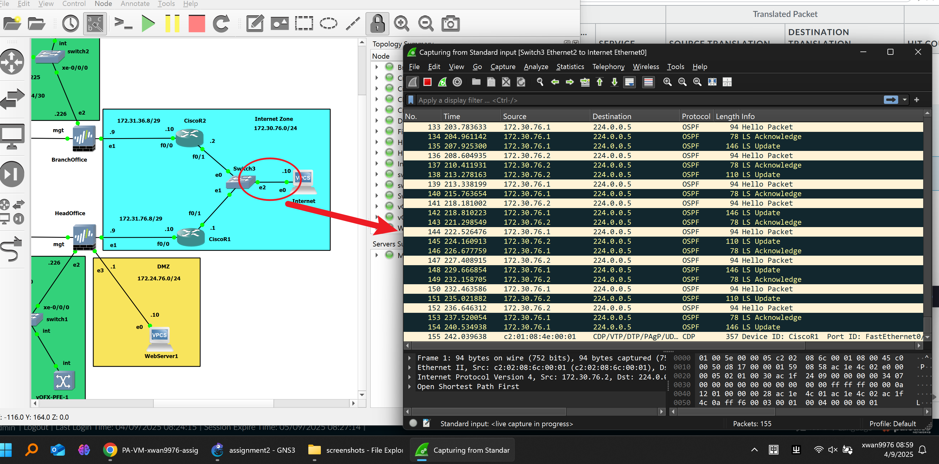
🌍 OSPF and ISP Network
The Internet layer was built with two simulated ISP routers using OSPF area 0.
Each router only advertised its directly connected networks to maintain routing isolation between internal and external domains.
Within each site:
-
The firewall’s Virtual Router participated in OSPF to exchange routes with the switch.
-
OSPF adjacency was verified through neighbor tables and database outputs.
Verification Command Example (Firewall):
show routing route virtual-router <vr-name> | match O
This ensured proper reachability between HQ and Branch networks over the VPN tunnel.
OSPF Packet Figure:
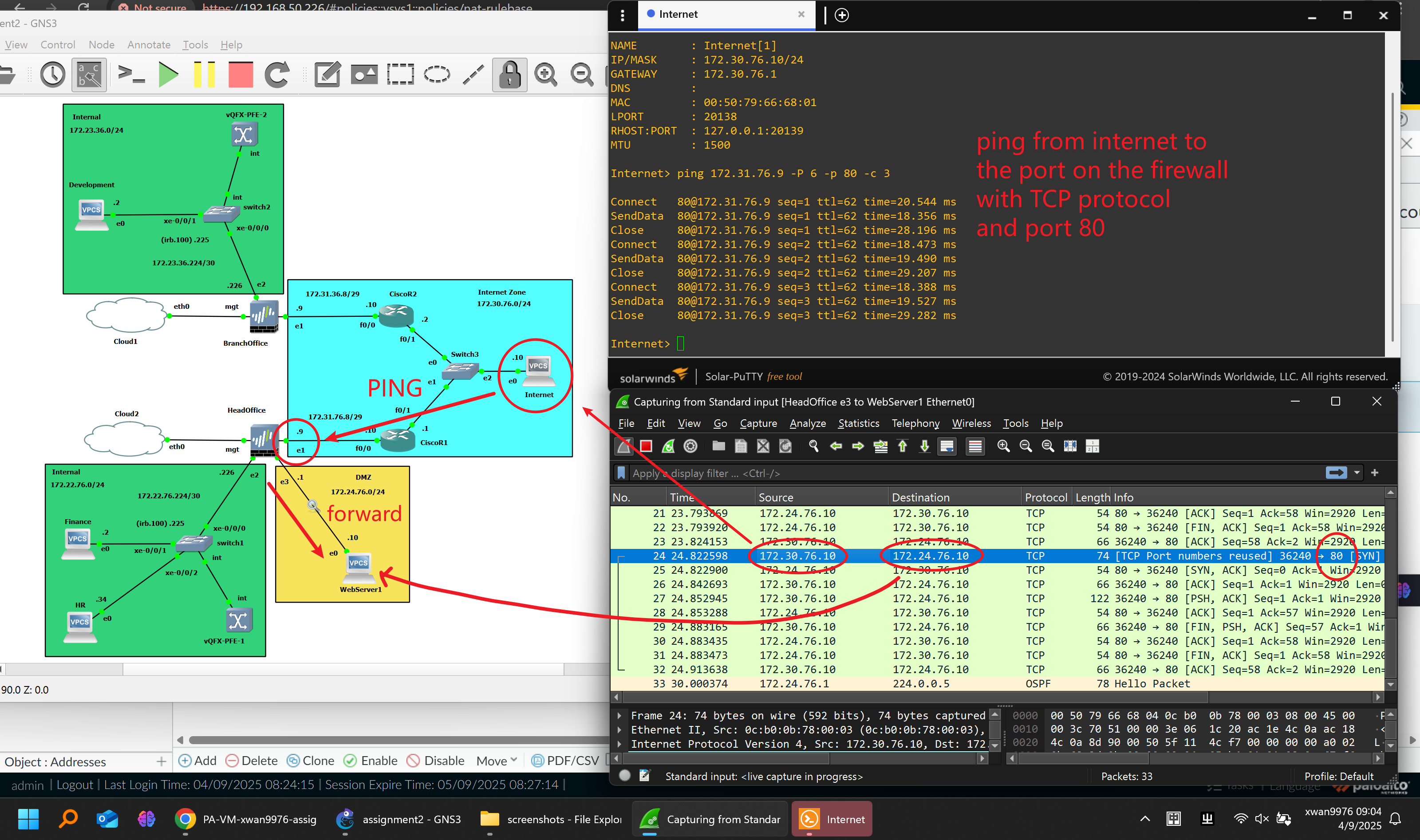
🔄 NAT Configuration
Dynamic Source NAT:
- Enabled for internal and DMZ networks to access the internet via the firewall’s public IP.
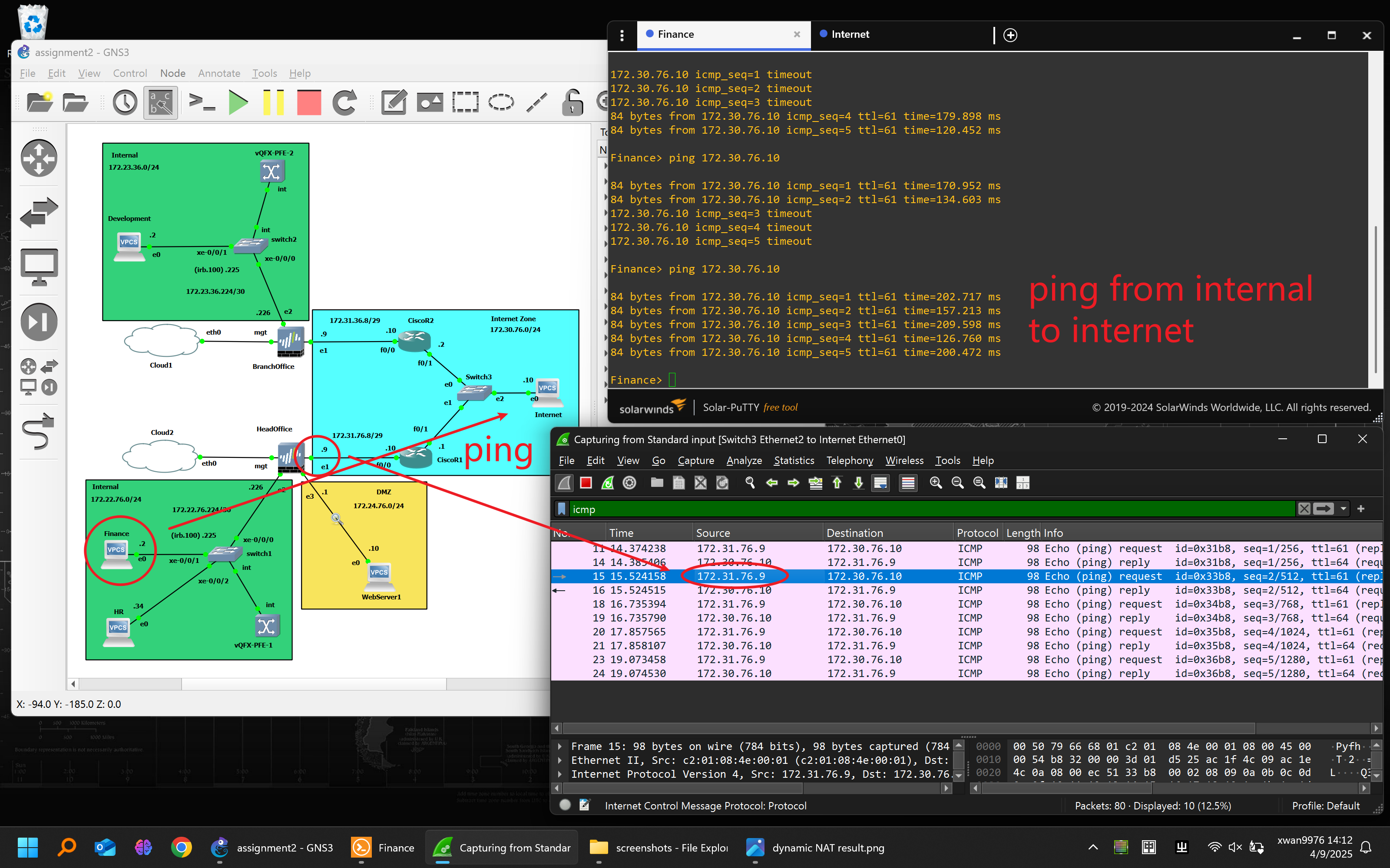
Destination NAT:
- Configured on the HQ firewall to expose the internal web server (
172.24.76.10) to external users through HTTPS on the untrust interface.
Testing:
-
Verified correct address translation in Session Browser and via packet capture.
-
External hosts successfully accessed the internal web server via public IP.
Destination NAT Testing Figure1:
Destination NAT Testing Figure2:
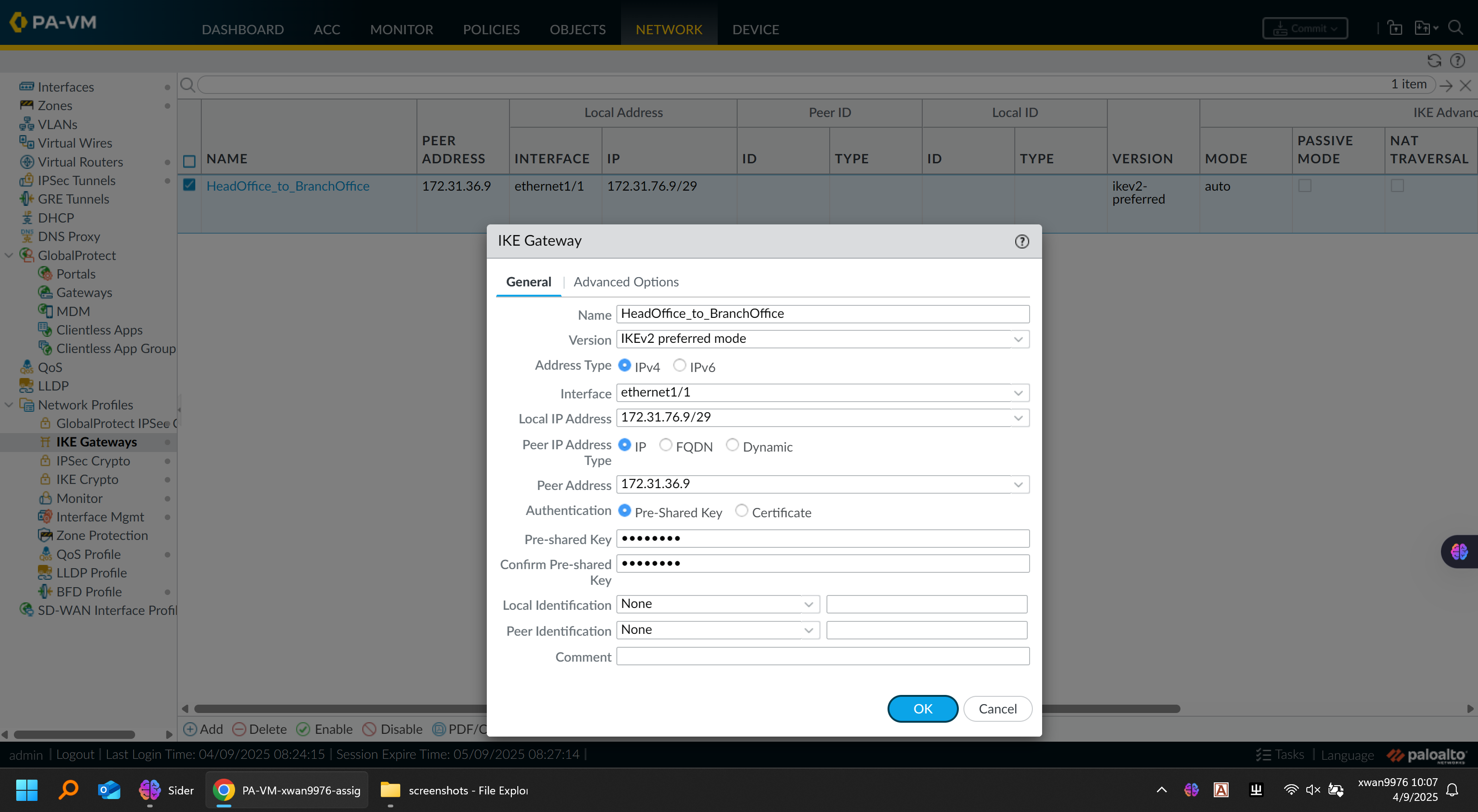
🔐 VPN Configuration
Implemented a site-to-site IPSec VPN between HQ and Branch offices:
IKE Configuration:
| Parameter | HQ | Branch |
|---|---|---|
| Local IP | 172.31.76.1 | 172.31.76.9 |
| Peer IP | 172.31.76.9 | 172.31.76.1 |
| Pre-shared Key | ***** | ***** |
| IKE Crypto | aes256-sha1, DH Group 14 | Same |
| IPSec Crypto | aes256-sha1, PFS enabled | Same |
IKE Gateway Configuration Figure:
IPSec Tunnel Configuration Figure:
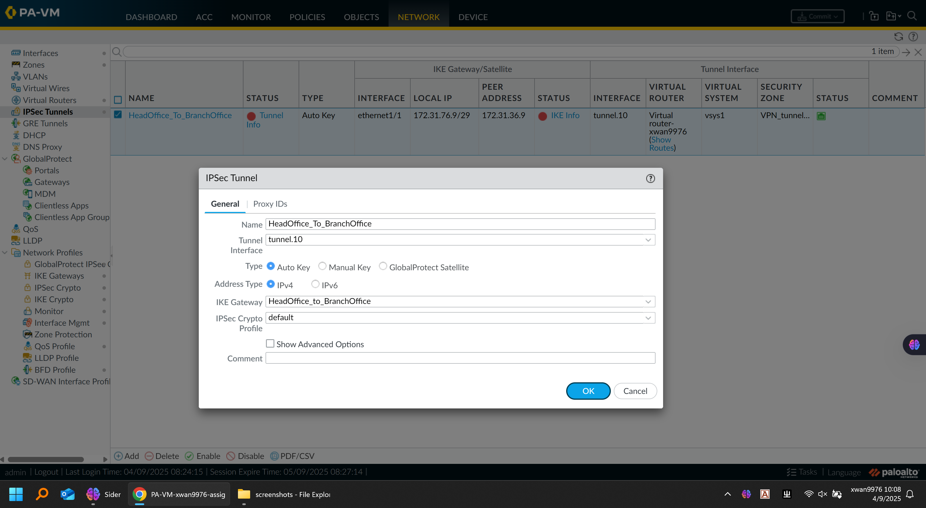
Tunnel Configuration:
-
Tunnel interfaces assigned to the VPN zone
-
Static routes added for remote internal subnets
-
Security policy allowing VPN zone-to-zone traffic
Verification:
-
VPN tunnel established successfully (green status)
-
ICMP and application traffic confirmed across both sites
-
Used
monitor trafficto validate encrypted flows
🧠 Reflection
This project replicated a full enterprise-grade design, integrating segmentation, routing, NAT, and secure tunneling within a unified simulation.
Key takeaways:
-
OSPF should only advertise directly connected networks to prevent conflicts.
-
VPN connectivity must be verified at both control and data plane levels.
-
NAT and firewall policies require careful ordering to ensure security and reachability.
-
The modular topology allows incremental testing — VLANs first, then NAT, then VPN.
Overall, this simulation mirrors the workflow of a real network deployment project, emphasizing design planning, implementation discipline, and verification methodology.
🧰 Tools & Environment
-
GNS3 running on Proxmox VE (Dell PowerEdge T320 HomeLab)
-
Palo Alto v11.0, Juniper vEX, Cisco 3725
-
Wireshark for packet inspection
-
Windows Server VM for web hosting and client simulation
GNS3 Platform:
🏁 Outcome
✅ End-to-end connectivity between HQ and Branch
✅ Isolated departmental VLANs and secure inter-zone routing
✅ Dynamic OSPF routing and reachability verification
✅ Functional NAT and public web access via DMZ
✅ Encrypted site-to-site VPN connectivity
This project showcases not just configuration skill but network architecture thinking — the ability to translate business requirements into secure, scalable designs.